Showing posts with label Basic mechanical equipments. Show all posts

Monday, September 12, 2011

Generator cooling system:


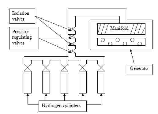
Normally generators are cooled by hydrogen gas. A cooling system consist some hydrogen cylinders, two pressure regulating valves, two isolation valves and a manifold.


Figure: Generator cooling system.


Working principle:

Ø      Hydrogen gas is supplied from gas cylinders.
Ø      Gas pressure is maintained at 100-125 psig by the 1st pressure regulating valve.
Ø      Gas pressure is maintained at lower value of 30 psig by 2nd pressure regulating valve.
Ø      Two insulation valves are used for insulation the supply.
Ø      Finally hydrogen enters into generator through a manifold and cools the entire temperature.


Megawatt and Mega VARs:


Megawatt:
            The megawatt is equal to one million (106) watts. Many events or machines produce or sustain the conversion of energy on this scale. For example: lightning strikes, large electric motors, large warships, such as aircraft carriers, cruisers, and submarines, engineering hardware, and some scientific research equipment, such as supercollider’s, and in the output pulses of very large lasers. A large residential or commercial building may consume several megawatts in electric power and heat.
The productive capacity of electrical generators operated by a utility company is often measured in MW.
Mega VARs:
            Mega VAR stands for Mega Volt*Amps Reactive. Although reactive power is not 'real' (i.e. it is not considered power at the source or destination), it still consists of current flowing in the transmission lines. When current flows in the line, power (real power) is lost due to I2R losses. When you are talking about Mega VARs, this power loss is significant and is a direct loss for the power company. This reactive power is usually caused by a company having a large inductive load (lots of motors). If it is bad enough, sometimes companies will put large capacitor banks in or near their factory to try and balance things out. If they don't, the power company may ask them to pay for the losses.


Here cosθ is known as power factor. It is the ratio of real power to apparent power. It lies between the number 0 and 1.


Kilowatt-hour (KWH):
            A kilowatt-hour is the amount of energy equivalent to a steady power of 1 kilowatt running for 1 hour. Generally it is known as unit.
Hence,
            1 unit electricity = 1 KWH power.

Generator:


In electricity generation, an electric generator is a device that converts mechanical energy to electrical energy. The source of mechanical energy may be a reciprocating or turbine steam engine, water falling through a turbine or waterwheel, an internal combustion engine, a wind turbine, a hand crank, compressed air or any other source of mechanical energy.


 Figure: Electric generator.
           
Working principle:

Electromagnetic induction is the production of voltage across a conductor moving through a magnetic field. So to get voltage, induction is very necessary. There are three conditions of proper induction.

1.      Conductor

2.      Magnetic fields and

3. Relative motion between them. 

 
3. Relative motion between them.    


Figure: Electromagnetic induction.
A metallic wire is warped around a metal bar called rotor. Rotor is connected with an external dc source for excitation. By the excitation, a magnetic field is produced where fluxes are flows from North Pole to South Pole.  When the rotor rotates the magnetic field also rotates. As a result the fluxes are cut by the conductors and voltage is induced from there. This is the Faraday’s law of electromagnetic induction.

Faraday's law of electromagnetic induction states that:
            “The electromotive force (EMF) produced around a closed path is proportional to the rate of change of the magnetic flux through any surface bounded by that path.”
Mathematically,
                         \mathcal{E} = -{{d\Phi_B} \over dt},
Where, \mathcal{E}is the electromotive force (emf) in volts.
ΦB is the magnetic flux in webers.
For the common but special case of a coil of wire, composed of N loops with the same area, Faraday's law of electromagnetic induction states that
 \mathcal{E} = - N{{d\Phi_B} \over dt}
Where,
\mathcal{E} is the electromotive force (emf) in volts.
N is the number of turns of wire.
ΦB is the magnetic flux in webers through a single loop.

Here, the negative sign indicates the direction which opposes the direction of motion according to Lenz’s law.

Applications of Faraday’s law:

Ø      Electrical generator
Ø      Moving coil microphone etc.

Power:
            Electric power is the rate at which electrical energy is transferred by an electric circuit. The SI unit of power is the watt. It is denoted by P.
Mathematically, P = VI = I2R
Where, V = voltage in volts (V)
             I = current in ampere (A)
             R = resistance in ohm (Ω)

In every power plant there are two types of power is generated.
1.      Megawatt (MW)
2.      MegaVARs (M-VAR)
Piping system:


Piping system is an essential part of a steam power plant. It is employed to transmit water, steam, air, oil and vapor from one position to others.

Types of piping system:
A power uses many fluids like water, air, oil, steam, gas etc during its operation. This requires a variety of integrated piping system mentioned below:

1.      Water piping: Raw water, feed water, condensate and condenser cooling water.
2.      Steam piping: Main, reheat, bleed exhaust steam.
3.      Blow of piping: Boiler, evaporator, feed treatment.
4.      Miscellaneous piping: Water treatment, service water, lubricating oil, drains compressed air etc.


                                                Figure:  Steam piping system

Materials for pipes:

Ø      Cast iron: Cast iron pipes are used underground for water and drainage system and in order to place where problem of corrosion is excessive. Cast iron pipes are used for water service up to a pressure of 15 kg/cm2.
Ø      Wrought iron: Wrought iron pipes are used for condensate, feed water and blow of lines. Such pipes are used for low and medium pressure range and should not be used when pressure is more than 250 psi.
Ø      Wrought steel: Most of the pipes used in power station are made of wrought steel. It is cheaper than others.
Ø      Alloys steel: For high temperature flow pipes are made of alloys steel. Chromium steel pipes are used for the temperature higher than 5250C. For temperature between 4000C-5250C carbons molybdenum steel may be used.
Ø      Copper and brass: Pipes made up of copper and brass are costly and are mostly used for oil lines. Brass pipe are used up to pressure 20 kg/cm2.


Sunday, September 11, 2011

Circulating Water Pump


Circulating Water Pump is briefly known as CWP.  The CWP are used for water circulation through out the system. One CWP have a capacity of 40,000 tones/hour and weight of 126 tones. Its power consumption is about 6 MW.

Main parts of CWP:
Ø      Pump casing
Ø      Shaft
Ø      Journal and Thrust bearings
Ø      Diffuser
Ø      Impeller
Ø      Electric motor

Application of centrifugal pump in power station:

Ø      Circulating water pump
Ø      Feed water pump
Ø      Condensate pump
Ø      Fire fighting pump
Ø      Demi water pump
Ø      LP and HP heater pump
Ø      Dosing pump etc.

Reciprocating pump:
                        A reciprocating pump is also known as a positive displacement pump, as it discharges a definite quantity of liquid during the displacement of its piston or plunger.

Comparison of Centrifugal and reciprocating pump:

Serial No:
Centrifugal pump
 Reciprocating pump
01
Suitable for large discharge and smaller heads.
Suitable for less discharge and higher heads.
02
Required less floor space and simple foundation.
Required more floor space and heavy foundation.
03
Maintenance cost is less.
Maintenance cost is high.
04
Can handle dirty water.
Can not handle dirty water.
05
Can run at high speed.
Can not run at high speed.
06
Its delivery is continuous.
Its delivery is pulsating.
07
No air vessel is required.
Air vessel is required.
08
Need priming.
Does not need priming.
09
It has less efficiency.
It has more efficiency.


Pumps:


Pumps are such a device, which transfer liquid from one place to another place by pressure difference.

Types of pump:
1.      Centrifugal pump
2.       Reciprocating pump

Centrifugal pump:
                        The pump which raises water or a liquid from a lower level to a higher level by the action of centrifugal force is known as centrifugal pump. A centrifugal pump is a rot dynamic pump that uses a rotating impeller to increase the pressure of a fluid. Centrifugal pumps are commonly used to move liquids through a piping system. The fluid enters the pump impeller along or near to the rotating axis and is accelerated by the impeller, flowing racially outward into a diffuser or volute chamber, from where it exits into the downstream piping system. Centrifugal pumps are used for large discharge through smaller heads.
Working principle: 
A centrifugal pump works by converting kinetic energy into potential energy measurable as static fluid pressure at the outlet of the pump. This action is described by Bernoulli's principle. With the mechanical action of an electric motor or similar, the rotation of the pump impeller imparts kinetic energy to the fluid through centrifugal force. The fluid is drawn from the inlet piping into the impeller intake eye and is accelerated outwards through the impeller vanes to the volute and outlet piping.